Release of ‘fwtool’ – firmware image manipulation tool

This is the initial public release of my ‘fwtool’ firmware manipulation tool.  The utility can be used to ‘unpack’ a firmware update “.bin” file into the component pieces (kernel, rootfs, (optional)wifi firmware), or to ‘pack’ these files back into a “.bin” firmware update file.

Here is a link to the code (source code, Linux x86, MacOS x86 binaries inside): fwtools_20100826c.tgz

WARNING: Patching/modifying firmware is not for everyone!  You could very easily BRICK your iSpot if you make a mistake!  Also, loading custom/patched firmware into your iSpot will likely VOID your warranty!  Proceed with caution!

The simplest use case is to unpack the “.bin” file to a directory which will contain the component files.  For example (use “-unpack infile.bin outdir” args):

$ ./fwtool -unpack iSpot_Software_080510.bin 080510_expanded
Wrote '080510_expanded/kernel.bin' successfully
Wrote '080510_expanded/rootfs.bin' successfully
Wrote '080510_expanded/wifi.bin' successfully
Wrote '080510_expanded/fwinfo.txt' successfully

“kernel.bin” is a Linux compressed kernel image (with ‘header app’ that decompresses it) targetted for an ARM CPU.

“rootfs.bin” is a JFFS2 root filesystem image (“kernel.bin” and “rootfs.bin” go together)

“wifi.bin” (not always part of “.bin” file) contains the firmware for the WiFi daughterboard. It is a Linux compressed kernel image (with built-in initrd ramdisk) targetted for a MIPS CPU.

At this point, you can inspect/patch/replace files in the output directory.  Once you are finished, you can pack them back up into a new “.bin” file.  For example (use “-pack indir outfile.bin” args): 

$ ./fwtool -pack 080510_expanded iSpot_Software_080510_new.bin
Loaded '080510_expanded/fwinfo.txt' successfully
Loaded '080510_expanded/kernel.bin' successfully
Loaded '080510_expanded/rootfs.bin' successfully
Loaded '080510_expanded/wifi.bin' successfully
Wrote iSpot_Software_080510_new.bin successfully

As described in “Why don’t firmware ‘downgrades’ work on the iSpot?“, the iSpot will refuse to install a firmware “.bin” file if the “svn version” is less than or equal to the current firmware’s version, or if the kernel/rootfs md5sum is found in a ‘blacklist’ table in the current firmware.

In order to allow for downgrading to old/blacklisted software, I’ve added a couple of options to the “-pack” process:

  • -svn-ver #### : Sets the output “.bin” file’s “svn version” value to “####”
  • -tweak-md5 : If specified, fwtool will modify the kernel/rootfs images in such a way that their md5sums will be different. This will allow them to get past the ‘blacklist’ test.


So, in order to modify an ‘illegal’ (old/blacklisted) “.bin” file in such a way that it will be accepted by the iSpot, first unpack the “.bin” to a directory.  Then, pack the directory back into a new “.bin” – specifying “-svn-ver ####” with a value that is larger than the currently running firmware’s version, and “-tweak-md5”:

$ ./fwtool -unpack iSpot_Software_080510.bin 080510_expanded
Wrote '080510_expanded/kernel.bin' successfully
Wrote '080510_expanded/rootfs.bin' successfully
Wrote '080510_expanded/wifi.bin' successfully
Wrote '080510_expanded/fwinfo.txt' successfully

$ ./fwtool -pack -svn-ver 1822 -tweak-md5 080510_expanded iSpot_Software_080510_allow_downgrade.bin
Loaded '080510_expanded/fwinfo.txt' successfully
Loaded '080510_expanded/kernel.bin' successfully
Loaded '080510_expanded/rootfs.bin' successfully
Loaded '080510_expanded/wifi.bin' successfully
Wrote iSpot_Software_080510_allow_downgrade.bin successfully

Disclaimer: information on this site is for educational purposes only, and intended to help iSpot owners experiment with their own devices. I do not condone any hacking for illegal purposes, such as stealing service, etc.

Posted in Uncategorized | 4 Comments

Why don’t firmware ‘downgrades’ work on the iSpot?

As you may have noticed, the iSpot’s web interface refuses to let you upload a firmware that isn’t “newer” that the current firmware.

When making this decision, the web interface looks to the “/etc/version.svn” file to see what the ‘current’ firmware version is.  The number stored in this file is the “####” part of the “2.0.0.0 [R#### … ]” software version string shown in the web interface’s firmware info page.

The code looks to the firmware update “.bin” file’s “svn version” header item to see what the new firmware’s version is (refer to “iSpot firmware download image file format” for details on the bin file header).

If the “.bin” file’s version is less than or equal to the current version, it refuses to accept the update.

Even if you were to ‘patch’ the “.bin” file’s header version to be greater than the current version (to make it appear ‘newer’), it may still fail to take the update.  The reason: “/bin/flash_program” contains a table of md5sums for older kernel/rootfs images that are ‘disallowed/blacklisted’.  If the incoming firmware’s kernel or rootfs md5sum matches any of the items in that table, then it will abort the flash programming process.

This blacklist allows Clear to fix ‘backdoors’ (such as the ability to enable telnet in older firmware).  Once you are on newer firmware, you can never go back to the old firmware with the backdoor.   At least that seems to be what they intended…

Disclaimer: information on this site is for educational purposes only, and intended to help iSpot owners experiment with their own devices. I do not condone any hacking for illegal purposes, such as stealing service, etc.

Posted in Uncategorized | 1 Comment

A closer look at flash memory partitions (with some insight on the firmware update process)

As I pointed out in my earlier article “Backing up the flash memory on your iSpot to your PC“, there are 10 ‘partitions’ on the flash memory chip in the iSpot (at least on my device). You can get a list of the partitions by dumping the contents of the file “/proc/mtd”:

# cat /proc/mtd
dev:    size   erasesize  name
mtd0: 00040000 00020000 "RedBoot"
mtd1: 00020000 00020000 "param"
mtd2: 00120000 00020000 "linux"
mtd3: 00600000 00020000 "rootfs"
mtd4: 00100000 00020000 "system"
mtd5: 00120000 00020000 "linux_2"
mtd6: 00600000 00020000 "rootfs_2"
mtd7: 00020000 00020000 "ver_1"
mtd8: 00020000 00020000 "ver_2"
mtd9: 0001f000 00020000 "FIS directory"
mtd10: 00001000 00020000 "RedBoot config"

 Here is a brief description of the partitions:

  • RedBoot : The RedBoot ‘boot loader’.  This contains the code that runs when you first power-ON your device.  It loads the Linux kernel and starts it (which in turn starts the main code for the iSpot)
  • param : Persistent parameters loaded into the iSpot at manufacturing time.  Information such as the WiMax MAC address, as well as radio ‘calibration’ data is stored here.  This information is very important!
  • linux : The Linux kernel portion of Firmware Image 1 (see Dual Firmware Images, below)
  • rootfs : The JFFS2 root filesystem portion of Firmware Image 1 (see Dual Firmware Images, below)
  • system : Persistent storage for ‘settings’ and other info that will remain even after a firmware upgrade
  • linux_2 : The Linux kernel portion of Firmware Image 2 (see Dual Firmware Images, below)
  • rootfs_2 : The JFFS2 root filesystem portion of Firmware Image 2 (see Dual Firmware Images, below)
  • ver_1 : The ‘version counter’ for Firmware Image 1 (see Dual Firmware Images, below)
  • ver_2 : The ‘version counter’ for Firmware Image 2 (see Dual Firmware Images, below)
  • FIS directory : RedBoot’s table of flash memory partitions (corresponds to /proc/mtd in Linux)
  • RedBoot config : Configuration for RedBoot (includes the ‘boot script’ that gets executed at startup)

Dual Firmware Images

The iSpot maintains two separate copies of Linux firmware in flash memory.  A single Firmware Image consists of two flash partitions : a Linux kernel, plus a JFFS2 root filesystem.

Only one copy of firmware is running at a time.  This is known as the ‘active’ Firmware Image (and the two flash partitions associated with it are the ‘active’ firmware partitions).

The other copy of the firmware is known as the ‘idle’ Firmware Image.

The iSpot uses the “ver_1” and “ver_2” partitions to decide which Firmware Image is ‘active’, and which is ‘idle’.  These partitions each hold a ‘counter’ value.  Whichever partition’s counter is higher is the one that is ‘active’ (and the lower counter value is ‘idle’).

For example, if the “ver_1” partition contains the value “26”, and the “ver_2” partition contains the value “27”, then the system knows that Firmware Image 2 is the ‘active’ one.  So, it chooses the “linux_2” partition to load the kernel, and “rootfs_2” for the JFFS2 root filesystem.  Firmware Image 1 (and its associated “linux” and “rootfs” partitions) are ‘idle’.

 Whenever a “firmware update” process takes place, the “/bin/flash_program” application find the ‘idle’ pair of partitions, and writes the new firmware there.  This avoids any possible problems with writing to the ‘active’ partition (for example, trying to modifiy files that are ‘in use’, or a power loss).  After the new firmware partitions are completely written/verified, the new firmware partitions are marked as ‘active’ (and the current one becomes ‘idle’).  This is done by taking the current ‘active’ partition’s ‘counter’ value (from the ‘active’ Firmware’s “ver” partition), adding one to it, then writing that to the ‘idle’ Firmware’s “ver” partition.

Going back to the above example, if “ver_1” contained “26” and “ver_2” contained “27” before the “firmware update” process (Firmware Image 2 is ‘active’), the new firmware would be written to the Firmware Image 1 partitions (“linux” and “rootfs”), as they are the ‘idle’ partitions.  When finished, “ver_1” would be updated with the value “28” (one higher than the ‘active’ partition’s “27”).

After the ‘active/idle’ switch, the iSpot reboots.  RedBoot will see that “ver_1” has the higher value (“28”), so will choose Firmware Image 1 as the ‘active’ firmware, and will boot with “linux” and “rootfs” (instead of “linux_2” and “rootfs_2”).


Disclaimer: information on this site is for educational purposes only, and intended to help iSpot owners experiment with their own devices. I do not condone any hacking for illegal purposes, such as stealing service, etc.

Posted in Uncategorized | Leave a comment

Backing up the flash memory on your iSpot to your PC

In case of future corruption of the flash memory chip on your iSpot (especially if you are ‘hacking’ your device), it’s a good idea to make a backup of the contents.  Hopefully, having this backup will make it possible to recover from ‘bricking’/etc in the future.

There are 10 ‘partitions’ on the flash memory chip in the iSpot (at least on my device).  You can get a list of the partitions by dumping the contents of the file “/proc/mtd”:

# cat /proc/mtd
dev:    size   erasesize  name
mtd0: 00040000 00020000 "RedBoot"
mtd1: 00020000 00020000 "param"
mtd2: 00120000 00020000 "linux"
mtd3: 00600000 00020000 "rootfs"
mtd4: 00100000 00020000 "system"
mtd5: 00120000 00020000 "linux_2"
mtd6: 00600000 00020000 "rootfs_2"
mtd7: 00020000 00020000 "ver_1"
mtd8: 00020000 00020000 "ver_2"
mtd9: 0001f000 00020000 "FIS directory"
mtd10: 00001000 00020000 "RedBoot config"

Each of the partitions has a pair of corresponding “device files” in “/dev” (one ‘character’ device, one ‘block’ device). For example, for “mtd0” you’ll find “/dev/mtd0” and “/dev/mtdblock0” files.

NOTE: Actually, “mtd10” doesn’t seem to have these device files by default. If you’d like to be able to access “mtd10” like other partitions, then type the following commands to create them:

mknod /dev/mtd10 c 90 20
mknod /dev/mtdblock10 b 31 10

To ‘back up’ a partition, use the “dd” command to dump the contents of the ‘character’ device file (“/dev/mtd0”, for example):

dd if=/dev/mtd0 of=/tmp/mtd0_backup.bin

Be careful about the “if=” (input file) and “of=” (output file) arguments – don’t mix them up!

Execute the “dd” command on each of the 10 partitions in order to have a complete backup.

The above example leaves the backup binary file in “/tmp”.  I’ve found that backing up to “/var/wwwroot” instead makes it easy to get the files off of the iSpot (and on to your PC).  “/var/wwwroot” points to the root of the iSpot’s web server, so you can download the backup file by downloading http://192.168.1.1/mtd0_backup.bin from your PC.

Don’t forget to remove the mtd backup files from “/var/wwwroot” once you’ve grabbed it using your PC!

In order to make things easier/less prone to error, I’ve written a little script to backup all of the partitions to files in “/var/wwwroot/mtd_backup”. Once you run the script, you can then browse to “http://192.168.1.1/mtd_backup”, then right-click on each link and “Save Target As…” to save each file.

Here’s a link to an mtd_backup.sh, and here’s the contents of the script:

#! /bin/sh

DESTDIR=/var/wwwroot/mtd_backup
mkdir -p $DESTDIR
echo "<HTML><body>" > $DESTDIR/index.html
echo "<br>Right-click and 'Save Target As...' on all of the following:<br>" >> $DESTDIR/index.html

let x=0
while [[ $x -le 10 ]]
do
    if [[ -c /dev/mtd$x ]]; then
        echo "--- Backing up mtd$x ---"
        dd if=/dev/mtd$x of=$DESTDIR/mtd$x.bin
        if [[ $? -ne 0 ]]; then
            echo "=== ERROR backing up mtd$x! Check free space in $DESTDIR! ==="
            exit 1
        fi
        echo "<br><br><A HREF=\"mtd$x.bin\">mtd$x.bin</A>" >> $DESTDIR/index.html
    fi
    let x=$x+1
done

echo "</body></html>" >> $DESTDIR/index.html
echo "=== Backup to $DESTDIR complete:"
ls -l $DESTDIR/mtd*.bin

The script creates a backup directory (“/var/wwwroot/mtd_backup”), backs-up all of the “/dev/mtd#” device files, and in the process creates an “index.html” file in “/var/wwwroot/mtd_backup” (makes it easier to download the files from your PC).

Don’t forget to remove the mtd backup files from “/var/wwwroot/mtd_backup” once you’ve grabbed them using your PC!

A future article will give some tips on recovering a device by making use of these backup files.


Disclaimer: information on this site is for educational purposes only, and intended to help iSpot owners experiment with their own devices. I do not condone any hacking for illegal purposes, such as stealing service, etc.

Posted in Uncategorized | 1 Comment

iSpot firmware download image file format

I’ve analyzed the structure of the “.bin” files used for firmware updates on the iSpot, and will document/update my findings below.

Here is a hex-dump of the beginning of a firmware update “.bin” file (this is from “iSpot_Software_080510.bin”):

00000000  49 4d 57 2d 43 36 31 35  57 00 00 00 00 00 00 00  |IMW-C615W.......|
00000010  00 00 00 00 00 00 00 00  00 00 00 00 00 00 00 00  |................|
00000020  04 03 02 01 01 09 09 04  fa 06 00 00 07 00 00 00  |................|
00000030  00 04 00 00 ec 96 11 00  c6 3d 6c 04 ad 30 9f 57  |.........=l..0.W|
00000040  eb 68 2f c1 f3 9f da 48  ec 9a 11 00 00 00 52 00  |.h/....H......R.|
00000050  33 dd ab bd 0f da 5d 02  f2 db c1 5e 35 bb 61 7e  |3.....]....^5.a~|
00000060  ec 9a 63 00 72 73 16 00  d9 ed ae eb 3d 90 b8 87  |..c.rs......=...|
00000070  9d 7e 10 93 a8 2d 52 4f  00 00 00 00 00 00 00 00  |.~...-RO........|
00000080  00 00 00 00 00 00 00 00  00 00 00 00 00 00 00 00  |................|
00000090  31 2e 31 2e 31 00 00 00  00 00 00 00 00 00 00 00  |1.1.1...........|
000000a0  00 00 00 00 00 00 00 00  00 00 00 00 00 00 00 00  |................|
000000b0  00 00 00 00 00 00 00 00  00 00 00 00 00 00 00 00  |................|
000000c0  00 00 00 00 ff ff ff ff  ff ff ff ff ff ff ff ff  |................|

Here is a description of the data at specific offsets:

0000-001e : Text description of image file (“name”)

001f-001f : I believe this is just a NULL terminator for the above string

0020-0023 : Used by the flash_program application to determine byte order (big- vs little- endian) of the file.  Should always be “04 03 02 01”.

0024-0027 : Version number (“vpos”): (“01 09 09 04” in this build: corresponds to “v1994”)

0028-002b : SVN version number (“svn”): same as value stored in this image’s “/etc/version.svn”, stored as a little-endian 32-bit value

002c-002c : Bitmask describing which ‘sub-files’ are contained in the .bin (“bintype”).

If bit 0 is set (bitmask 0x01), then the image contains a KERNEL.

If bit 1 is set (bitmask 0x02), then the image contains a jffs2 root filesystem (ROOTFS).

If bit 2 is set (bitmask 0x04), then the image contains a WiFi firmware image (WIFI).

If bit 3 is set (bitmask 0x08), then the image contains an unknown 4th sub-file image (UNDEF).

002d-002f : Unknown/undefined

KERNEL info:

0030-0033 : Offset into .bin file to start of kernel image (if “bintype” KERNEL bit is set) (little-endian 32-bit)

0034-0037 : Size of kernel image (if “bintype” KERNEL bit is set) (little-endian 32-bit)

0038-0047 : MD5 hash of kernel image (if “bintype” KERNEL bit is set)

ROOTFS info:

0048-004b : Offset into .bin file to start of jffs2 root filesystem image (if “bintype” ROOTFS bit is set) (little-endian 32-bit)

004c-004f : Size of jffs2 root filesystem image (if “bintype” ROOTFS bit is set) (little-endian 32-bit)

0050-005f : MD5 hash of jffs2 root filesystem image (if “bintype” ROOTFS bit is set)

WIFI info:

0060-0063 : Offset into .bin file to start of WiFi firmware image (if “bintype” WIFI bit is set) (little-endian 32-bit)

0064-0067 : Size of WiFi firmware image (if “bintype” WIFI bit is set) (little-endian 32-bit)

0068-0077 : MD5 hash of WiFi firmware image (if “bintype” WIFI bit is set)

UNDEF info:

0078-008f : Appears to be room for fourth ‘sub-file’ info

0090-???? : If “bintype” WIFI bit is set, then the ASCII (NULL terminated) version string for the WiFi image is stored here (max length unknown).

????-00c3 : Unknown (currently NULL bytes)

Looking at the specific file header show in the hex-dump above, you can see that the “svn” version number is 0x000006fa (“1786” decimal).

The “.bin” file contains a kernel image, a jffs2 root filesystem image, and a WiFi firmware image (because “bintype” is “07”, so all three file type bits are set).

The KERNEL image starts at offset 0x00000400 into the “.bin” file, and is 0x1196ec bytes long.

The ROOTFS image starts at offset 0x119aec into the “.bin” file, and is 0x00520000 bytes long.

The WIFI image starts at offset 0x00639aec into the “.bin” file, and is 0x00167372 bytes long.


Sub-file image format

The KERNEL image is a standard compressed kernel image (with a ‘header applet’ which decompresses the kernel payload and jumps to it). It is for an ARM architecture CPU.

The ROOTFS image is a JFFS2 filesystem image. This was likely created either directly using “mkfs.jffs2”, or by dumping the contents of the flash chip partition after the JFFS2 image was created there.

The WIFI image is a standard compressed kernel image with an embedded init ramdisk (“initrd”). This kernel is for a MIPS architecture CPU.

Manipulating firmware update image

I plan on releasing some utilities for unpacking/repacking the contents of a firmware update image.  Once finished, a link will be provided here.

EDIT: The firmware manipulation utility has been released. See this article : “Release of ‘fwtool’ – firmware image manipulation tool“.

Disclaimer: information on this site is for educational purposes only, and intended to help iSpot owners experiment with their own devices. I do not condone any hacking for illegal purposes, such as stealing service, etc.

Posted in Uncategorized | 1 Comment

Adding a serial console port to the iSpot (with iSpot teardown)

This is my first blog entry.  I’m not much of a writer, but will hopefully describe things well enough for people to understand.

Thanks to my friend Al for the hardware help.

I wanted to add a serial port to my iSpot, so I’d have access to the RedBoot serial console (runs before the kernel loads).  This will hopefully make it safer for experimentation – I should be able to recover from ‘bricking’ by using the serial console/RedBoot commands.

What follows are step-by-step instructions for adding a serial port to your iSpot.  I am assuming that you have basic hardware knowledge, and are very comfortable with disassembling hardware (and feel confident that you can reassemble it!)

WARNING: You could very easily DESTROY your iSpot if you make a mistake!  Also, modifying your iSpot in any way will likely VOID your warranty!  Proceed with caution!

Here’s the iSpot with battery cover removed.

Remove the 3 indicated screws, then use fingernail/other thin tool to separate the front/back plastic (they snap together).

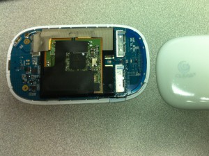
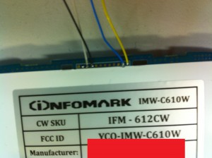
Here’s the iSpot with the plastic cover removed (showing “component side” of board – the side opposite the battery compartment):

Pop the PC board out of the plastic (be careful in the area of the power switch).  Make a note of the orientation of the board (use mini-usb port as a reference for when you reassemble it).

Here is the PC board removed, showing the battery compartment side:

Notice the 12-pin header along the top – we’ll be attaching the serial port to some of these pins.  Sadly, the serial port signals from the CPU don’t connect directly to the pins on this header – they go through some ‘zero ohm’ resistors, which are NOT populated by default.  So, to enable the serial port, you need to install those resistors (or just short the connections with small wires or solder-blobs).

The serial port resistors are located underneath the WiFi daughtercard.  So, this must be removed.  Flip the board back over, and carefully disconnect the white antenna cable near the top of the board (sorry, I don’t have a photo).  Then, carefully remove the plastic cover that holds-down the WiFi daughtercard.  Do this by pushing the plastic snaps through from the back side, one at a time.  NOTE that the interconnect between the main board and daugtercard is along the bottom of the daughtercard (when viewing with antenna cable along the top).  It came apart pretty easily for us.

Here’s a photo of the main board (component side) with daughtercard removed (daughtercard has been ‘flipped up’ in this photo – notice the antenna wire sticking out at the ‘bottom’ of the daughtercard – it’s along the top when the board is flipped back over/oriented correctly):

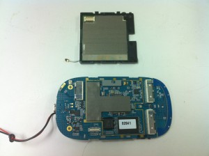
(ignore the wires coming out the left-side of the main board in the above photo – we temporarily soldered some on to the battery contacts so we could connect to a bench power supply)

The resistors we need to populate are underneath the small rectangular grey piece of foam (with a notch in it) along the top of the main board (was separating the main board and daughtercard).  NOTE: it is taped-down with double-sided tape.  When we removed it, the double-sided tape was left behind.  We needed to remove the tape in order to get access to the resistors, and destroyed the tape in the process.  You may want to be more careful – although it wasn’t a problem to put back together (WiFi daughtercard causes enough of a compression fit to hold the foam in place).

Here’s a photo with that foam removed, and a circle around the pads for the two resistors which need to be installed:

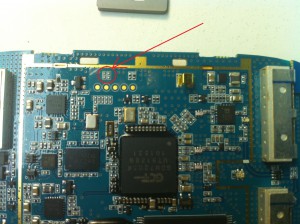
The two resistor sites are outlined by white silkscreen.  In this photo, they are oriented vertically – one resistor is on the left, one on the right.  You need to install resistors (or short wires/solder blobs) vertically – connecting the left-top pad with the left-bottom pad, and (separately) connecting the right-top pad with the right-bottom pad.

Once that is done, reverse your steps to reconnect the WiFi daughtercard.  Be careful about the alignment of the interconnect between the two boards.  Also, don’t forget to re-connect the white antenna cable.

Now, flip the main board over again (showing battery-compartment side, with 12-pin header along the top).  Notice that the left-side pin is square, where the rest are round.  The square pin is pin #1.

We need to solder wires to the UART “TX” (output from CPU to PC) and “RX” (input from PC to CPU) lines.  NOTE that these are 3.3V signals – you will probably need a level-shifter in order to connect to a PC serial port.  Do NOT connect a standard PC serial port with +/- 12V signals directly to these points!

The level-shifter we use at work requires a 3.3V power supply (in addition to the TX/RX lines), so we decided to tap-into 3.3V and GND signals (also found on the 12-pin header).  Here’s the pin numbers for each of the signals:

  • Pin 3 – 3.3V
  • Pin 4 – GND
  • Pin 11 – UART TX (output of iSpot CPU’s serial port – to PC)
  • Pin 12 – UART RX (input to iSpot CPU’s serial port – from PC)

Here’s a photo with the wires attached (sorry they are blurry, and we didn’t use ‘correct’ colors for power/GND):

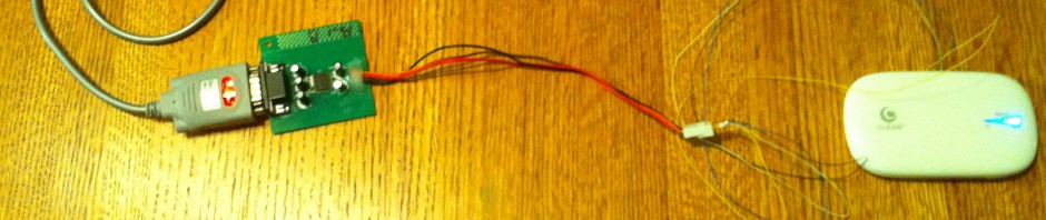
We cut some small notches into the plastic case (where the top/bottom plastic parts snap together) to make room for the wires to come out.  Then we put all the pieces back together.  Here is the result:

And here it is connected to our serial level converter (converts 3.3V TTL levels to PC-compatible RS-232 levels):

Finally, here’s the serial console output when RedBoot starts up (UART config: 115200/8/n/1) (I hit Control-C to interrupt):

+INTEL FLASH:89:1b

RedBoot(tm) bootstrap and debug environment [REDBOOT]

Non-certified release, version UNKNOWN – built 11:10:44, Apr 16 2010

Platform: GCT GSK7205 (GDM7205) 

Copyright (C) 2000, 2001, 2002, Red Hat, Inc.

***********************************************************

*       I N F O M A R K   W i M A X    R o u t e r        *

*       SDRAM: 64MByte, SDRAM Clock Delay: 0x0809         *

*       FLASH: 16MByte, S(0xc0000000) – E(0xc0ffffff)     *

***********************************************************

RAM: 0xd4000000-0xd8000000, [0xd4008000-0xd7f51000] available

FLASH: 0xc0000000 – 0xc0ffffff 4 x 0x8000 blocks 127 x 0x20000 blocks

Redboot-Turn On WiFi and Make Power Hold High

== Executing boot script in 1.000 seconds – enter ^C to abort

^C

RedBoot> ^C

RedBoot> ^C

RedBoot> ^C

RedBoot> help

Manage aliases kept in FLASH memory

   alias name [value]

Set/Query the system console baud rate

   baudrate [-b <rate>]

Manage machine caches

   cache [ON | OFF]

Display/switch console channel

   channel [-1|<channel number>]

Compute a 32bit checksum [POSIX algorithm] for a range of memory

   cksum -b <location> -l <length>

Check all availave Dram area

   dramchk

Display (hex dump) a range of memory

   dump -b <location> [-l <length>] [-s] [-1|2|4]

Execute an image – with MMU off

   exec [-w timeout] [-b <load addr> [-l <length>]]

        [-r <ramdisk addr> [-s <ramdisk length>]]

        [-c “kernel command line”] [<entry_point>]

Manage FLASH images

   fis {cmds}

Manage configuration kept in FLASH memory

   fconfig [-i] [-l] [-n] [-f] [-d] | [-d] nickname [value]

Execute code at a location

   go [-w <timeout>] [-c] [entry]

Help about help?

   help [<topic>]

Display command history

   history

Load a file

   load [-r] [-v] [-d] [-m <varies>]

        [-b <base_address>] <file_name>

Compare two blocks of memory

   mcmp -s <location> -d <location> -l <length> [-1|-2|-4]

Copy memory from one address to another

   mcopy -s <location> -d <location> -l <length> [-1|-2|-4]

Fill a block of memory with a pattern

   mfill -b <location> -l <length> -p <pattern> [-1|-2|-4]

Reset the system

   reset

Display RedBoot version information

   version

Display (hex dump) a range of memory

   x -b <location> [-l <length>] [-s] [-1|2|4]

RedBoot>

That’s about it – good luck!

Disclaimer: information on this site is for educational purposes only, and intended to help iSpot owners experiment with their own devices. I do not condone any hacking for illegal purposes, such as stealing service, etc.

Posted in Hardware | Leave a comment