This is my first blog entry. I’m not much of a writer, but will hopefully describe things well enough for people to understand.
Thanks to my friend Al for the hardware help.
I wanted to add a serial port to my iSpot, so I’d have access to the RedBoot serial console (runs before the kernel loads). This will hopefully make it safer for experimentation – I should be able to recover from ‘bricking’ by using the serial console/RedBoot commands.
What follows are step-by-step instructions for adding a serial port to your iSpot. I am assuming that you have basic hardware knowledge, and are very comfortable with disassembling hardware (and feel confident that you can reassemble it!)
WARNING: You could very easily DESTROY your iSpot if you make a mistake! Also, modifying your iSpot in any way will likely VOID your warranty! Proceed with caution!
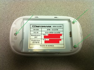
Here’s the iSpot with battery cover removed.
Remove the 3 indicated screws, then use fingernail/other thin tool to separate the front/back plastic (they snap together).
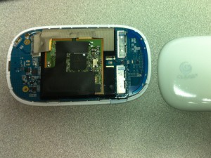
Here’s the iSpot with the plastic cover removed (showing “component side” of board – the side opposite the battery compartment):
Pop the PC board out of the plastic (be careful in the area of the power switch). Make a note of the orientation of the board (use mini-usb port as a reference for when you reassemble it).
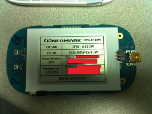
Here is the PC board removed, showing the battery compartment side:
Notice the 12-pin header along the top – we’ll be attaching the serial port to some of these pins. Sadly, the serial port signals from the CPU don’t connect directly to the pins on this header – they go through some ‘zero ohm’ resistors, which are NOT populated by default. So, to enable the serial port, you need to install those resistors (or just short the connections with small wires or solder-blobs).
The serial port resistors are located underneath the WiFi daughtercard. So, this must be removed. Flip the board back over, and carefully disconnect the white antenna cable near the top of the board (sorry, I don’t have a photo). Then, carefully remove the plastic cover that holds-down the WiFi daughtercard. Do this by pushing the plastic snaps through from the back side, one at a time. NOTE that the interconnect between the main board and daugtercard is along the bottom of the daughtercard (when viewing with antenna cable along the top). It came apart pretty easily for us.
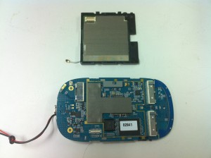
Here’s a photo of the main board (component side) with daughtercard removed (daughtercard has been ‘flipped up’ in this photo – notice the antenna wire sticking out at the ‘bottom’ of the daughtercard – it’s along the top when the board is flipped back over/oriented correctly):
(ignore the wires coming out the left-side of the main board in the above photo – we temporarily soldered some on to the battery contacts so we could connect to a bench power supply)
The resistors we need to populate are underneath the small rectangular grey piece of foam (with a notch in it) along the top of the main board (was separating the main board and daughtercard). NOTE: it is taped-down with double-sided tape. When we removed it, the double-sided tape was left behind. We needed to remove the tape in order to get access to the resistors, and destroyed the tape in the process. You may want to be more careful – although it wasn’t a problem to put back together (WiFi daughtercard causes enough of a compression fit to hold the foam in place).
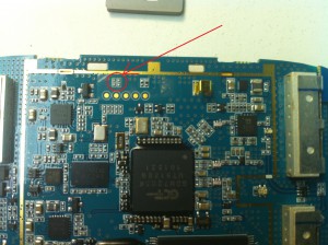
Here’s a photo with that foam removed, and a circle around the pads for the two resistors which need to be installed:
The two resistor sites are outlined by white silkscreen. In this photo, they are oriented vertically – one resistor is on the left, one on the right. You need to install resistors (or short wires/solder blobs) vertically – connecting the left-top pad with the left-bottom pad, and (separately) connecting the right-top pad with the right-bottom pad.
Once that is done, reverse your steps to reconnect the WiFi daughtercard. Be careful about the alignment of the interconnect between the two boards. Also, don’t forget to re-connect the white antenna cable.
Now, flip the main board over again (showing battery-compartment side, with 12-pin header along the top). Notice that the left-side pin is square, where the rest are round. The square pin is pin #1.
We need to solder wires to the UART “TX” (output from CPU to PC) and “RX” (input from PC to CPU) lines. NOTE that these are 3.3V signals – you will probably need a level-shifter in order to connect to a PC serial port. Do NOT connect a standard PC serial port with +/- 12V signals directly to these points!
The level-shifter we use at work requires a 3.3V power supply (in addition to the TX/RX lines), so we decided to tap-into 3.3V and GND signals (also found on the 12-pin header). Here’s the pin numbers for each of the signals:
- Pin 3 – 3.3V
- Pin 4 – GND
- Pin 11 – UART TX (output of iSpot CPU’s serial port – to PC)
- Pin 12 – UART RX (input to iSpot CPU’s serial port – from PC)
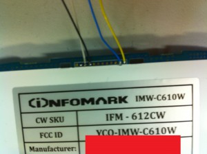
Here’s a photo with the wires attached (sorry they are blurry, and we didn’t use ‘correct’ colors for power/GND):
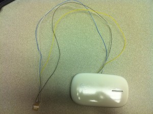
We cut some small notches into the plastic case (where the top/bottom plastic parts snap together) to make room for the wires to come out. Then we put all the pieces back together. Here is the result:
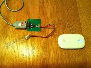
And here it is connected to our serial level converter (converts 3.3V TTL levels to PC-compatible RS-232 levels):
Finally, here’s the serial console output when RedBoot starts up (UART config: 115200/8/n/1) (I hit Control-C to interrupt):
+INTEL FLASH:89:1b
RedBoot(tm) bootstrap and debug environment [REDBOOT]
Non-certified release, version UNKNOWN – built 11:10:44, Apr 16 2010
Platform: GCT GSK7205 (GDM7205)
Copyright (C) 2000, 2001, 2002, Red Hat, Inc.
***********************************************************
* I N F O M A R K W i M A X R o u t e r *
* SDRAM: 64MByte, SDRAM Clock Delay: 0x0809 *
* FLASH: 16MByte, S(0xc0000000) – E(0xc0ffffff) *
***********************************************************
RAM: 0xd4000000-0xd8000000, [0xd4008000-0xd7f51000] available
FLASH: 0xc0000000 – 0xc0ffffff 4 x 0x8000 blocks 127 x 0x20000 blocks
Redboot-Turn On WiFi and Make Power Hold High
== Executing boot script in 1.000 seconds – enter ^C to abort
^C
RedBoot> ^C
RedBoot> ^C
RedBoot> ^C
RedBoot> help
Manage aliases kept in FLASH memory
alias name [value]
Set/Query the system console baud rate
baudrate [-b <rate>]
Manage machine caches
cache [ON | OFF]
Display/switch console channel
channel [-1|<channel number>]
Compute a 32bit checksum [POSIX algorithm] for a range of memory
cksum -b <location> -l <length>
Check all availave Dram area
dramchk
Display (hex dump) a range of memory
dump -b <location> [-l <length>] [-s] [-1|2|4]
Execute an image – with MMU off
exec [-w timeout] [-b <load addr> [-l <length>]]
[-r <ramdisk addr> [-s <ramdisk length>]]
[-c “kernel command line”] [<entry_point>]
Manage FLASH images
fis {cmds}
Manage configuration kept in FLASH memory
fconfig [-i] [-l] [-n] [-f] [-d] | [-d] nickname [value]
Execute code at a location
go [-w <timeout>] [-c] [entry]
Help about help?
help [<topic>]
Display command history
history
Load a file
load [-r] [-v] [-d] [-m <varies>]
[-b <base_address>] <file_name>
Compare two blocks of memory
mcmp -s <location> -d <location> -l <length> [-1|-2|-4]
Copy memory from one address to another
mcopy -s <location> -d <location> -l <length> [-1|-2|-4]
Fill a block of memory with a pattern
mfill -b <location> -l <length> -p <pattern> [-1|-2|-4]
Reset the system
reset
Display RedBoot version information
version
Display (hex dump) a range of memory
x -b <location> [-l <length>] [-s] [-1|2|4]
RedBoot>
That’s about it – good luck!
Disclaimer: information on this site is for educational purposes only, and intended to help iSpot owners experiment with their own devices. I do not condone any hacking for illegal purposes, such as stealing service, etc.

